AC roller table motors
|
Contrary to standard motors, the roller table motors running in switch or inverter operation are built in a more robust way and are better insulated. All motors correspond to the Regulations for Electrical Machines according to VDE 0530.
The classic roller table motor reaches its maximum torque when switching-on, i. e. the maximum torque can be virtually equated with the starting torque with speed zero. As the short circuit cage of the rotor consists of a diecasting special alloy, the motor features a soft characteristic line, the so-called roller table characteristic. |
|
Shall the motor be operated at the inverter with variable frequency, we recommend the selction of a motor with “hard” torque or speed characteristic.
This characteristic is achieved by an aluminium diecasting rotor. The operating point of the motor is always located in the final area of the characteristic line. In this case, the acceleration torque amounts to a maximum of 75% of the breakdown torque. |
rollertable characteristicshard characteristicssemi-hard characteristics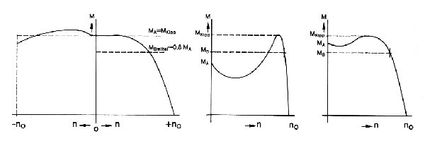
opposed current |
AC roller table motors
|
... achieve starting torques of up to 5,300 Nm with switch operation or capacities of up to 90 KW with inverter operation. In case of inquiries or placing orders, please indicate the type of the power supply.
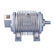
The three-phase A C motor with gilled housing offers the advantage that it does not have a fanwhich is speed-dependent. A fan which is connected to the motor shaft loses its efficiency with low speeds and frequent switching processes. With the gilled motor, however, the dissipation of the lost heat is effected solely by heat radiation over the large housing surface. |
|
|
Technical dates, construction
|
Type KDR, suitable for inverter supply
System of protection : IP 54 Structural shape :IM 1001 (B3) and IM 3001 (B5)
Low voltage up to 500 volts, 50 Hz |
|
From Types KDR20F to KRD66M, the terminal box is located on top of the B side. From Types KRD34K to KDR66M, the shaft end is cylindrical or has a conical shape in a ratio from 1 to 10! |
Assesment at 400 V, 50 Hz
| Type | power | torque (Nm) | current expressed | power- | mass mom. | |||
| KDR | bei 400 V, 50 Hz | factor | of inertia | |||||
| kW | nom. | acc. | max. | rated current | acc. current | cos φ | kgm2 | |
| n syn = 1000 min-1 (6-poles) | ||||||||
| 15 D 09-6 | 0,7 | 7 | 20 | 26 | 2,5 | 5,2 | 0,60 | 0,0075 |
| 15 D 12-6 | 0,96 | 9,5 | 27 | 35 | 3,10 | 6,5 | 0,61 | 0,0095 |
| 15 E 16-6 | 1,26 | 12,5 | 36 | 47 | 3,40 | 8,1 | 0,68 | 0,0125 |
| 17 E 14-6 | 1,56 | 15,5 | 45 | 60 | 4,20 | 10,0 | 0,69 | 0,0175 |
| 20 F 13-6 | 2,44 | 24,0 | 64 | 85 | 6,00 | 14,0 | 0,69 | 0,0310 |
| 20 F 18-6 | 3,45 | 34,0 | 90 | 120 | 8,20 | 19,5 | 0,70 | 0,0425 |
| 20 G 22-6 | 3,68 | 36,0 | 113 | 150 | 8,80 | 24,0 | 0,71 | 0,0520 |
| 24 G 18-6 | 4,88 | 48,0 | 135 | 180 | 11,00 | 28,5 | 0,74 | 0,0900 |
| 24 G 22-6 | 5,79 | 57,0 | 173 | 230 | 12,50 | 35,0 | 0,77 | 0,1100 |
| 24 H 28-6 | 8,13 | 80,0 | 218 | 290 | 17,00 | 43,0 | 0,79 | 0,1400 |
| 27 H 24-6 | 10,26 | 100,0 | 285 | 380 | 21,00 | 58,0 | 0,80 | 0,1700 |
| 27 J 36-6 | 14,37 | 140,0 | 430 | 570 | 28,50 | 87,0 | 0,82 | 0,2600 |
| 30 J 34-6 | 20,11 | 195,0 | 600 | 800 | 39,50 | 115,0 | 0,83 | 0,3600 |
| 30 K 41-6 | 24,76 | 240,0 | 750 | 1000 | 47,00 | 150,0 | 0,85 | 0,4300 |
| 34 K 41-6 | 30,94 | 300,0 | 980 | 1300 | 59,00 | 195,0 | 0,85 | 0,8000 |
| 37 K 42-6 | 39,20 | 380,0 | 1300 | 1700 | 74,00 | 260,0 | 0,86 | 1,3500 |
| 42 K 46-6 | 48,73 | 470,0 | 1750 | 2300 | 90,00 | 350,0 | 0,87 | 2,3000 |
| n syn = 750 min-1 (8-poles) | ||||||||
| 15 D 09-8 | 0,45 | 6 | 17 | 22 | 2,1 | 3,8 | 0,50 | 0,0075 |
| 15 D 12-8 | 0,60 | 8,0 | 23 | 30 | 2,80 | 5,0 | 0,50 | 0,0095 |
| 15 E 16-8 | 0,82 | 11,0 | 30 | 40 | 3,50 | 6,2 | 0,50 | 0,0125 |
| 17 E 14-8 | 1,13 | 15,0 | 39 | 51 | 4,20 | 7,5 | 0,56 | 0,0175 |
| 20 F 13-8 | 1,88 | 25,0 | 64 | 85 | 5,30 | 11,0 | 0,64 | 0,0350 |
| 20 F 18-8 | 2,64 | 35,0 | 90 | 120 | 7,00 | 15,0 | 0,66 | 0,0455 |
| 20 G 22-8 | 3,39 | 45,0 | 115 | 150 | 8,40 | 19,0 | 0,68 | 0,0590 |
| 24 G 18-8 | 3,95 | 52,0 | 130 | 173 | 9,90 | 22,0 | 0,67 | 0,1000 |
| 24 G 22-8 | 4,93 | 65,0 | 165 | 220 | 12,50 | 27,0 | 0,71 | 0,1250 |
| 24 H 28-8 | 5,73 | 75,0 | 210 | 275 | 14,00 | 34,0 | 0,71 | 0,1550 |
| 27 H 24-8 | 7,26 | 95,0 | 265 | 350 | 17,00 | 41,0 | 0,70 | 0,2150 |
| 27 J 35-8 | 8,79 | 115,0 | 390 | 520 | 23,00 | 60,0 | 0,65 | 0,3100 |
| 30 J 34-8 | 12,61 | 165,0 | 600 | 800 | 29,00 | 87,0 | 0,76 | 0,5100 |
| 30 K 45-8 | 16,16 | 210,0 | 830 | 1100 | 40,00 | 130,0 | 0,67 | 0,6800 |
| 34 K 43-8 | 19,63 | 255,0 | 1020 | 1350 | 50,00 | 165,0 | 0,64 | 1,0000 |
| 37 K 43-8 | 25,78 | 335,0 | 1350 | 1800 | 62,00 | 205,0 | 0,68 | 1,6000 |
| 42 K 46-8 | 35,65 | 460,0 | 1900 | 2500 | 83,00 | 280,0 | 0,70 | 2,8000 |
Assesment at 400 V, 20 Hz
Max. possible voltage 690 V with special isolation.
| Type | power | torque (Nm) | current expressed | power- | mass mom. | |||
| KDR | bei 400 V, 20 Hz | factor | of inertia | |||||
| kW | nom. | acc. | max. | rated current | acc. current | cos φ | kgm2 | |
| n syn = 240 min-1 (10-poles) | ||||||||
| 34 K 43-10 | 8,50 | 350,0 | 980 | 1300 | 24,50 | 62,00 | 0,650 | 1,00 |
| 37 K 43-10 | 16,30 | 680,0 | 1350 | 1800 | 44,00 | 80,00 | 0,670 | 1,70 |
| 42 K 46-10 | 18,00 | 750,0 | 1800 | 2400 | 42,00 | 100,00 | 0,690 | 2,80 |
| 50 K 40-10 | 23,38 | 1000,0 | 2600 | 3400 | 59,00 | 145,00 | 0,700 | 5,40 |
| 50 L 58-10 | 32,00 | 1300,00 | 3800 | 5000 | 75,00 | 195,00 | 0,720 | 7,80 |
| 58 L 55-10 | 49,20 | 2000,0 | 5300 | 7000 | 106,00 | 265,00 | 0,730 | 15,50 |
| 66 L 56-10 | 67,01 | 2700,0 | 7200 | 9600 | 148,00 | 350,00 | 0,750 | 33,50 |
| 66 M 75-10 | 89,35 | 3600,0 | 9800 | 13000 | 196,00 | 480,00 | 0,750 | 44,50 |
Accessories
Thermal winding protection
The best protection against harmful overheating of the winding is achieved by controlling the winding temperature directly. For this purpose, alternatively three thermal contracts, PTC-resistor temperature probes or Pt multiplier resistors each can be installed at the end windings of the three winding branches. This can be carried out on request and will be charged additionally. Tachometers, pulse generatorsShould the recording of the current speed be required during actuation, a tachometer or pulse generator can be mounted on the second shaft end on request. |
Brakes
Also on request, roller table drives can be supplied as braking motors and drum brakes or spring pressure disk brakes are used.
|


