THREE-PHASE MOTORS
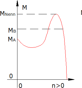
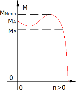
In contrast to standard motors, roller table motors are more robust. These motors comply with the regulations for electrical machines according to VDE 0530, but are better insulated for switching or converter operation. The classic roller table motor operates with maximum torque when it is switched on, which means almost at the point of operation the maximum torque can be equated with the starting torque. In the Klose motor, the squirrel-cage of the rotor consists of a special die-cast alloy, and its groove shape can also be specially configured if required. Above this, the motor achieves its soft characteristic (cf. Diagram 1.1 below left), the so-called roller table characteristic. If the motor is operated on the converter with variable frequency, we recommend choosing a motor with a “hard” torque-speed characteristic (see diagram 1.2 below, middle) or a “half-hard” torque-speed characteristic (see diagram 1.3, bottom right).
The properties of die-cast aluminum rotors ensure that the motor’s operating point is always in the last area of the characteristic curve. In this case, the acceleration torque is a maximum of 75% of the breakdown torque. Roller table motors are acceleration motors and achieve starting torques of up to 5300 [Nm] in switching operation or outputs of up to 90 [kW] in converter operation. Accelerator motors are designed to allow a high overload capacity (up to four times). This makes them especially suitable for reversing operations.
When making inquiries or placing orders, please indicate your requirements and the type of feed.
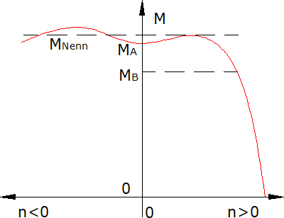
1.1 Characteristics of the roller table motor
1.2 hard characteristic
1.3 soft characteristic
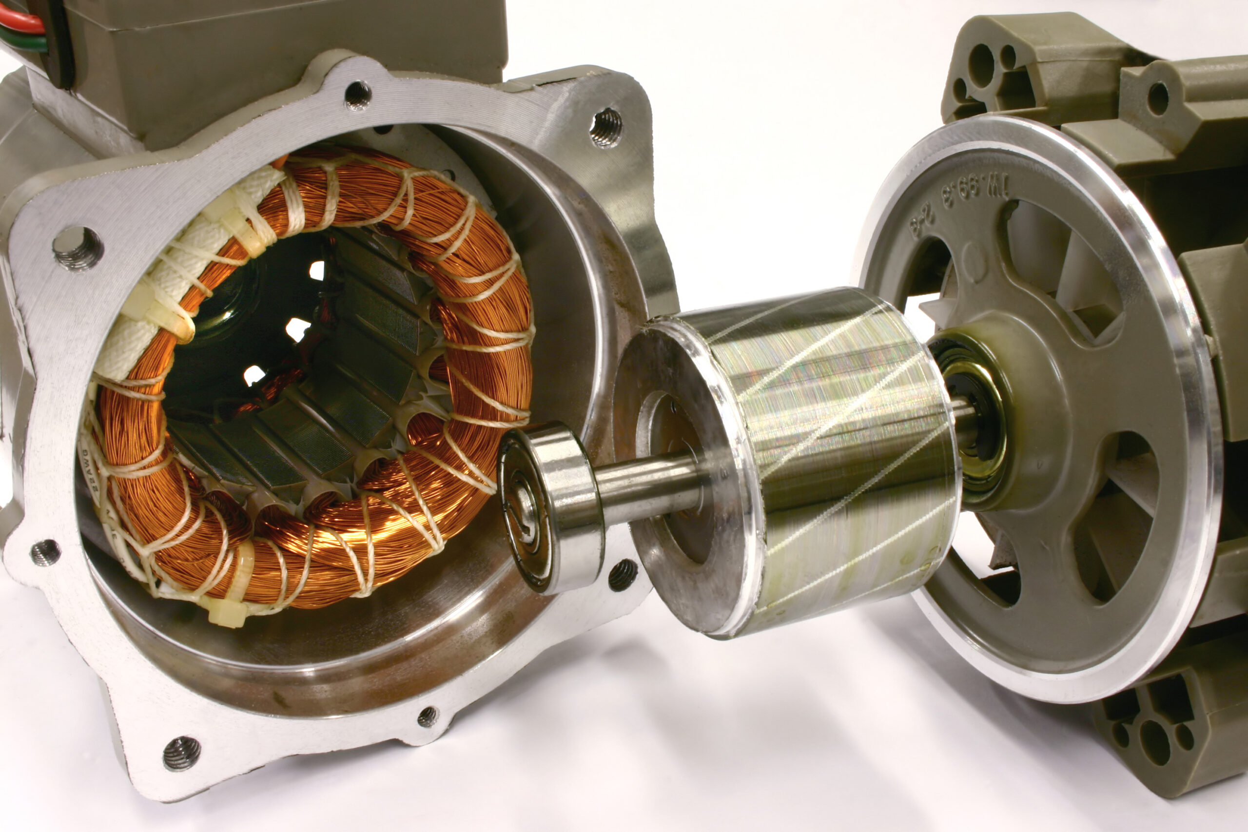
The Ring Finned Motor
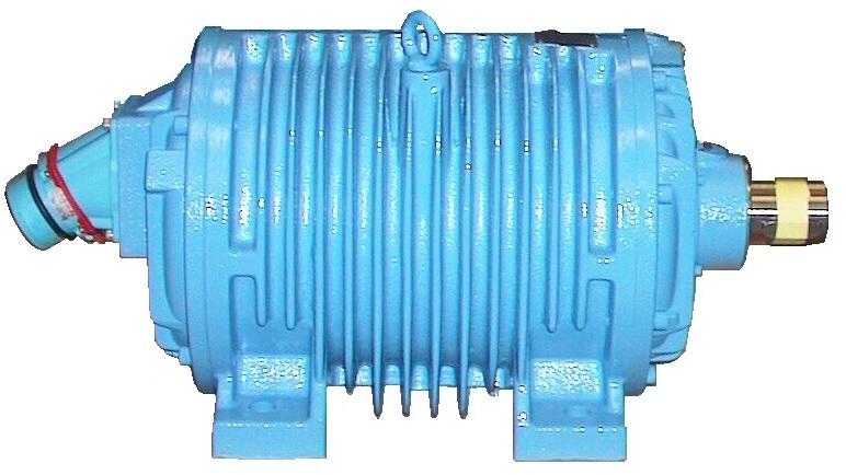
The standard KLOSE type roller table motor has a housing with annular ribs. The advantage is that this motor has no fan. A fan that is firmly coupled to the motor shaft loses its effectiveness at low speeds, as well as with frequent switching operations, because there is hardly any cooling, steady, air flow. In the case of the ring-fin motor, on the other hand, the heat loss is dissipated exclusively by thermal radiation and by convection via the enlarged housing surface with the cooling fins, which run parallel to the rising air. There is also no need to seal the motor against dust and moisture introduced by the fan.
The result is a motor with the (internal) designation KDR (short-circuit three-phase ring-ribbed motor). However, its connection dimensions are comparable to DIN motors. Consequently, it is also possible to bring a KLOSE special design into a DIN housing or to bring a DIN stator into a ring-finned housing.
Sizes
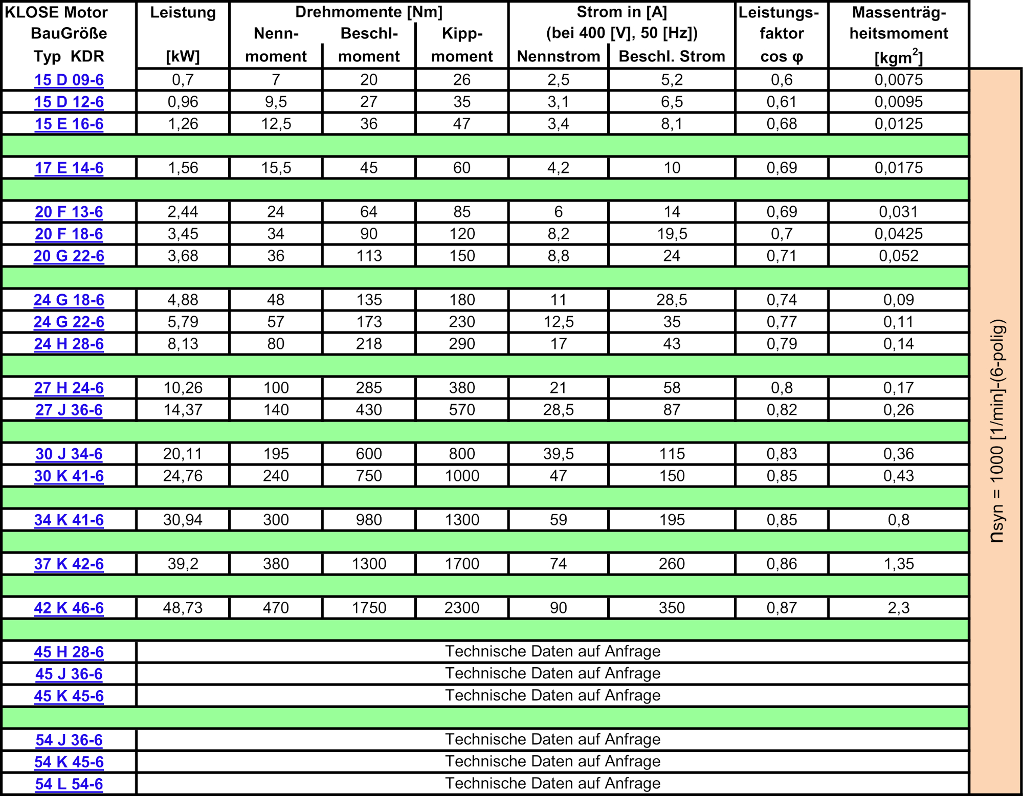
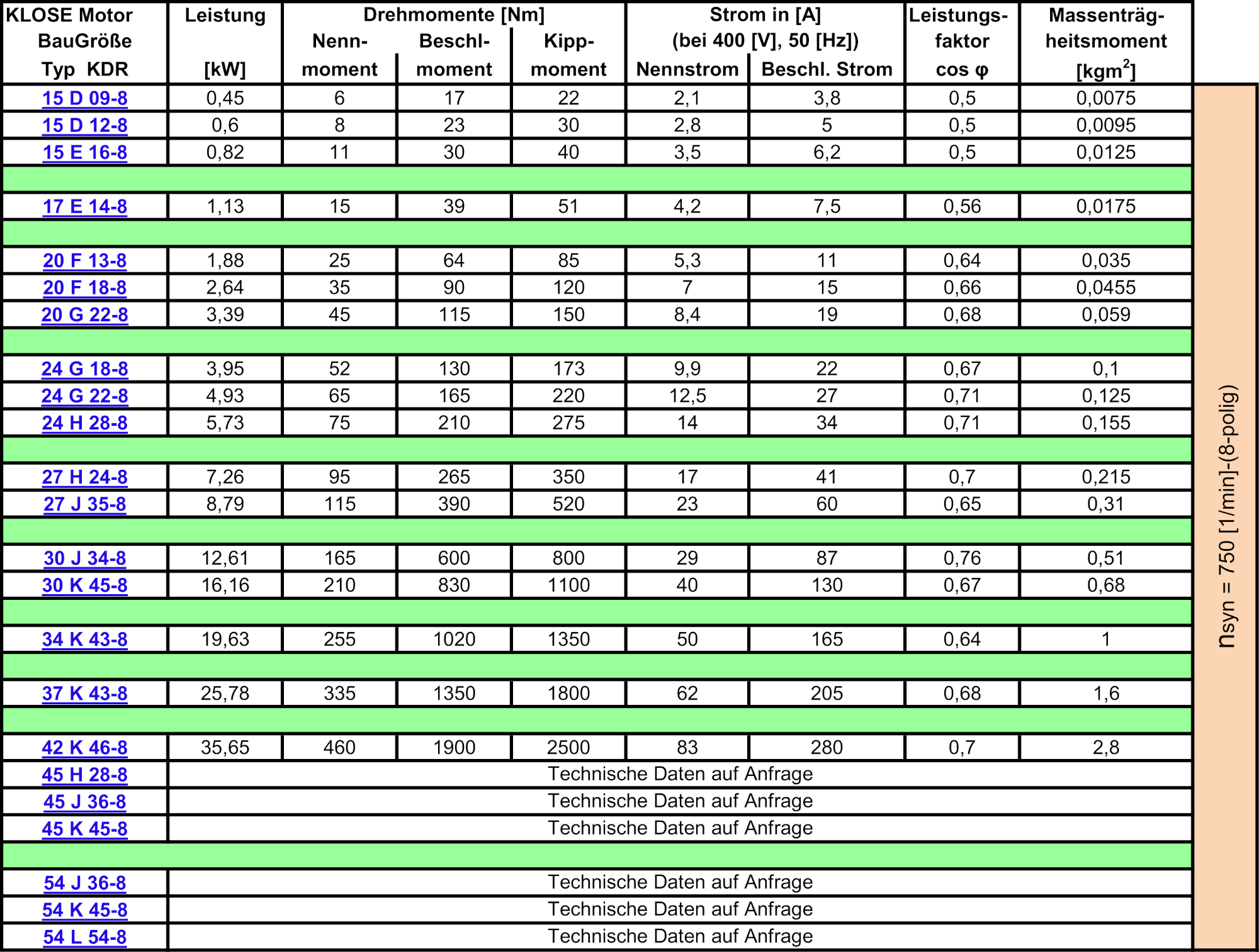
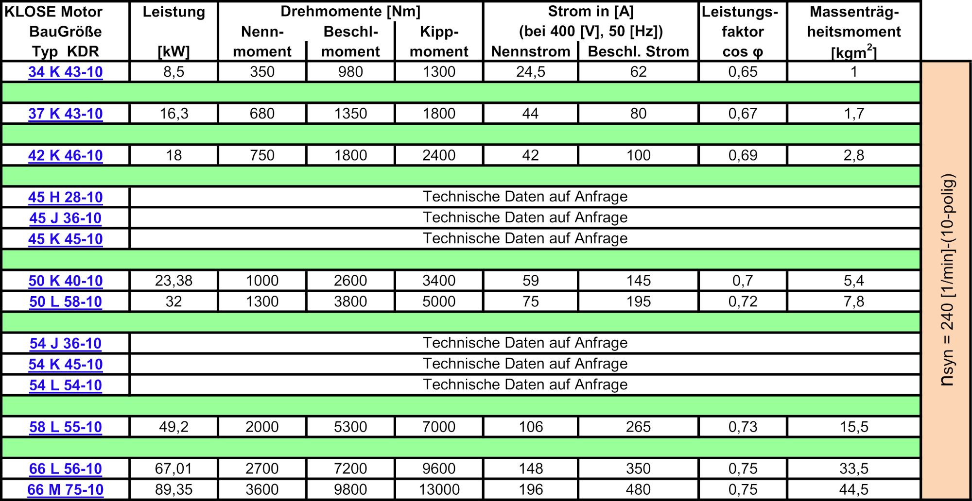
Ratings are listed below with designations from KDR15 to KDR66 (this corresponds to DIN size 80 to size 400). All motors are suitable for converter and mains operation. The operating mode should be known for project planning. There are different housing lengths (D; E; …J) to adapt the motor size to the power / torque. and different pole pairs are used to coordinate the desired speed.
The attached tables are intended to provide an overview of the standard specifications of built engines.
Examples of performance data for ring-fin motors at 400 V, 50 Hz
Examples of performance data for ring-finned motors at 400 V, 20 Hz (direct drives)
The max. possible mains voltage 690 V when using special insulation.
Constructive design and special
Degree of protection / terminal box
Fundamentally, KLOSE ring-finned motors are designed in protection class: IP 54. Increased degrees of protection are achieved through special seals. The ring-finned motor benefits from the fact that it does not have a fan on the operator side. With interchangeable parts for the cast models, designs in IM 1001 (B3) and IM 3001 (B5) are possible.
In addition, KLOSE has developed motor brackets for the B5 design for connection to its own gearboxes. This particularly robust KLOSE flange closes the A-side of the motor (with a cavity for a winding head) and has widely spaced screw holes for connection to the gearbox. The wall thicknesses of the flanges are dimensioned in such a way that the motor does not break off, even under impact loads.
The terminal box position can be freely selected. For some motors there are also position plates for a terminal box at the rear.
Thermal winding protection
The safest protection against destructive overheating of the winding is direct control of the winding temperature. For this purpose, three thermal contacts, PTC thermistors or Pt measuring resistors can be installed separately in the winding overhangs for each winding phase.
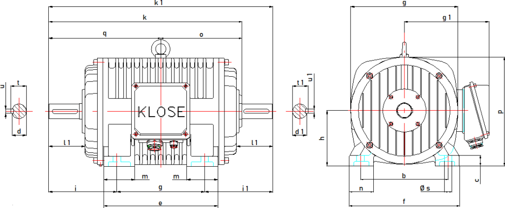
Dimensions