Worm Gears
(ASNG) Worm Gears
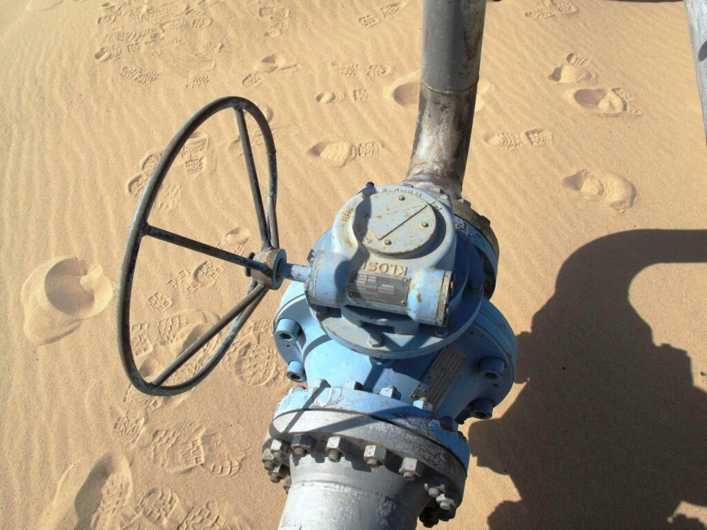
Fittings worm gears are used worldwide in a wide variety of areas. Mention should be made e.g. B. hydraulic engineering, petroleum plants, general. chemical industry, breweries, in natural gas distribution as well as conventional power plants and nuclear power plants. The insert can be swiveled as a rotary rotor over 360 degrees or only over a predetermined angular range. They operate valves to regulate or shut-off valves and flaps to stop the flow.
The worm gears can be driven either manually or via electric motors (with remote control) to operate slides or valves. The translation of the entire unit can also be designed widely by means of a countershaft. Although this extends the actuation time, it increases the accuracy of the control and reduces the costs for an electric drive for the adjustment.
ASNG, Construction Implementations
Our gearbox housings are made of gray cast iron or nodular cast iron. Degree of protection IP 68 according to EN 60526. The worm is made of case-hardened alloy steel. It is hardened, straightened and ground and inserted into the housing in tapered roller bearings.
The worm wheel is made of spherical cast iron and is fitted with plain bearings. With smaller valve gears, up to a size of 9,000 [Nm], the wheel hub can also be installed in tapered roller bearings. This increases the precision of the gears and, in particular, the excessive torque at the start of actuation of the valve gear almost completely disappears.
Instead of nodular iron, the worm wheel can be made of special bronze in the contact area. The center of the worm wheel is designed in such a way that a spline for a coupling socket with a tooth profile according to DIN 5480 can be introduced. The associated socket can be rotated tooth by tooth, which enables adaptation to the connected machine. As a rule, we also offer the customer-specific version of the socket.
However, it is also possible to use tension rings. This makes it easier and increases the coordination of the angular position of the valve gear and the connected unit. Finally, any parallel key is also possible for direct connection.
Different Versions of Construktion
The components of the valve gears are largely standardized. This opens up countless possibilities for the installation position. But it also requires compliance with an exact designation to describe the desired finish.
Shown in the illustration below: a.) Standard valve gearbox with foot flange; b.) Valve gearbox with inserted shaft and foot flange; c.) Valve gear with angle foot and d.) Valve gear with angle foot and lever as well as inserted shaft.
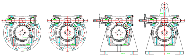
There are now two further variants: the choice of the input shaft for left or right rising and the installation position of the drive shaft on the left or right side.
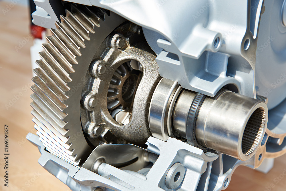
The tapered roller bearing of the worm shaft is clearly visible in the sectional views. However, KLOSE has also worked on the bearing of the worm wheel in order to reduce the toothing play. By storing the wheel, however, friction torque when starting can also be reduced. Especially after a total standstill, sticking can occur. The roller bearing also offers advantages when the gearbox is used in regular operation.
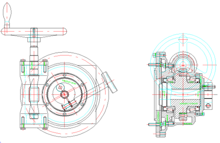
The attached illustration shows a valve gear with handwheel, roller bearing of the hub and a locking device to fix the set position.