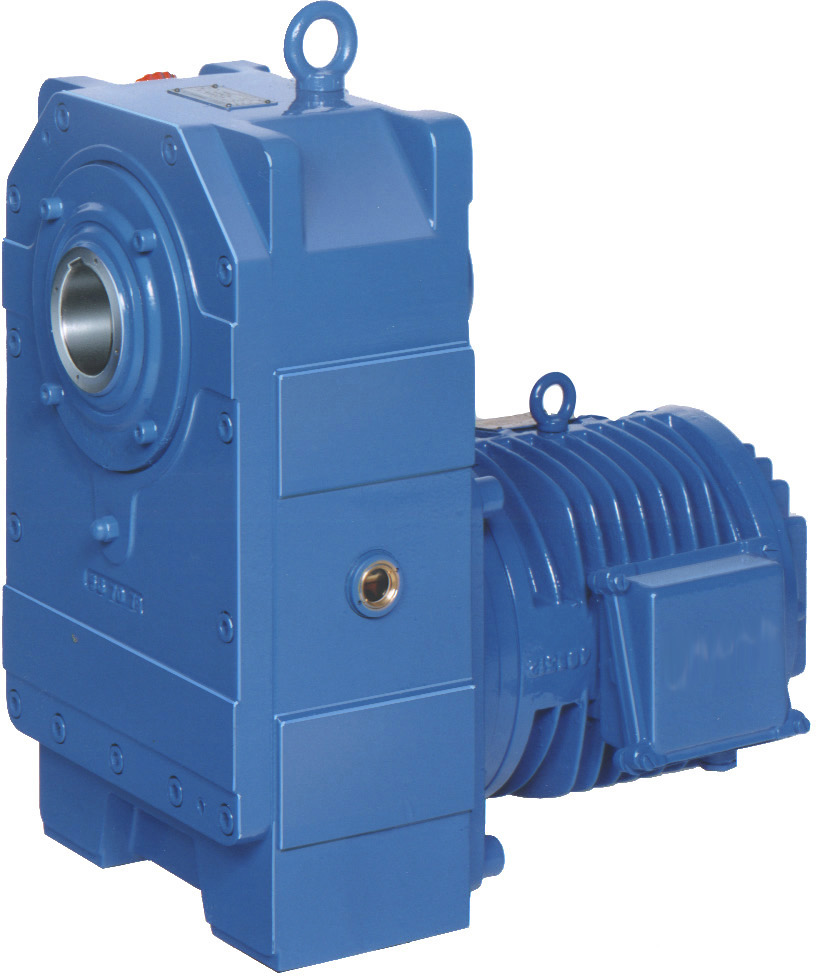
Transmissions with Hollow Shaft (B5)
Transmissions with Hollow Shaft (B5)
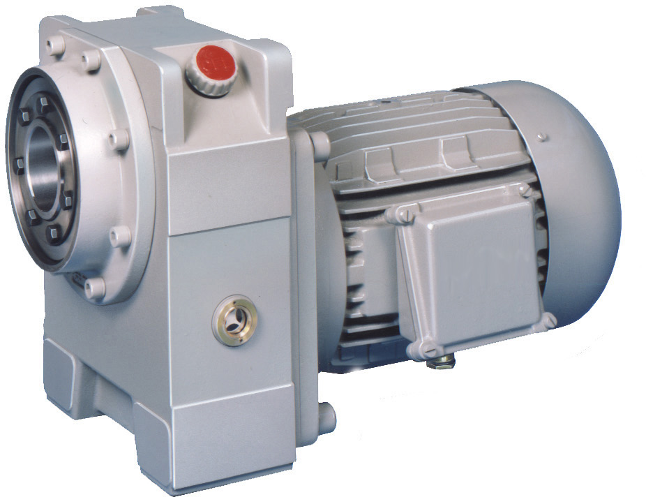
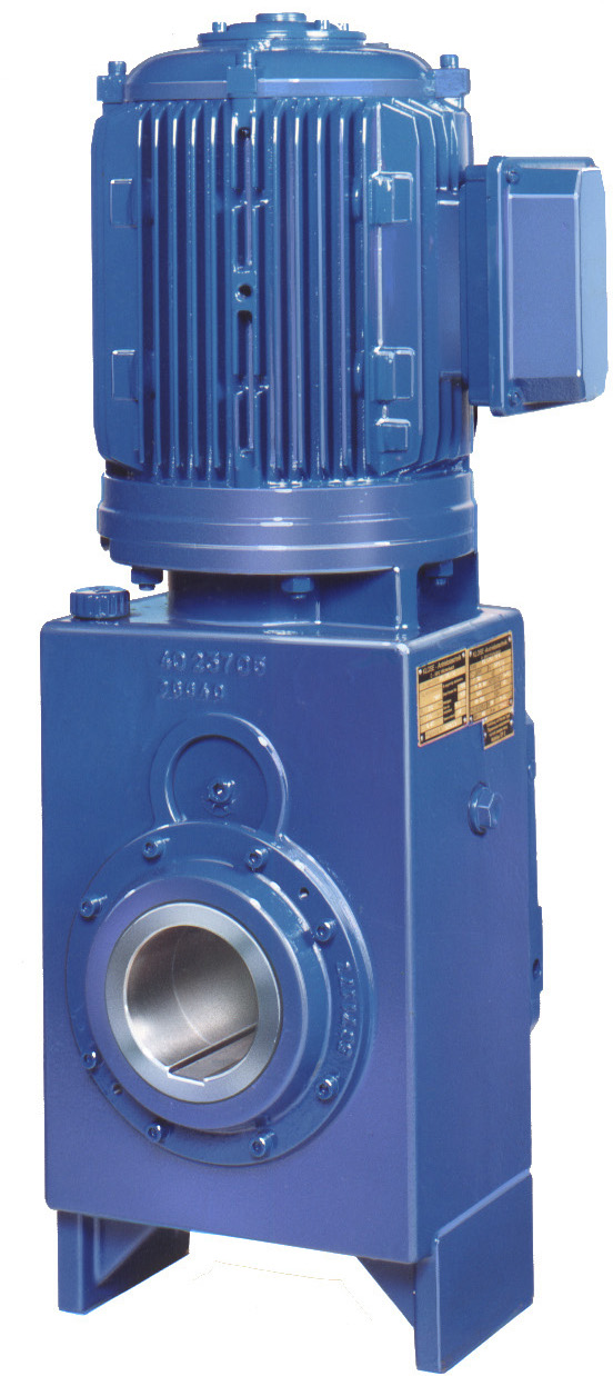
Hollow shaft gears are pushed onto the (shaft) journal of the working machine with the motor. This eliminates the need for a coupling to connect the gearbox and motor (shorter installation space). To absorb the reaction torque, the gearboxes have lateral stops with different distances. Reaction torque can be derived directly from the housing, or via a cast torque arm (so the motor doesn’t rotate around the pulley). As a third option, the reaction forces are dissipated by a (extended) support bolted under the gearbox
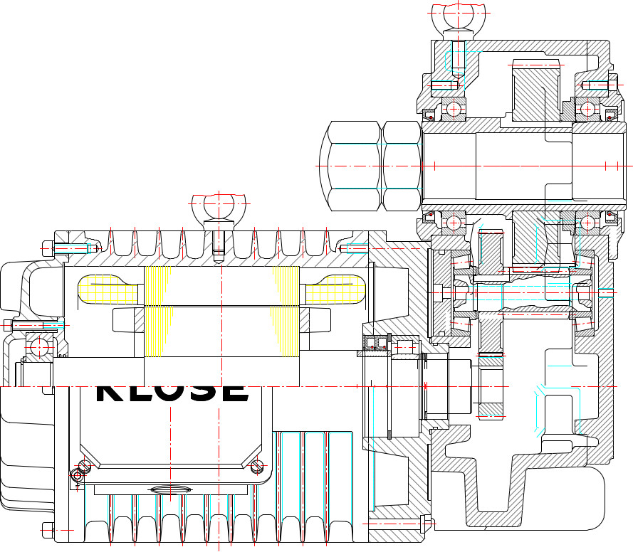
Construktion
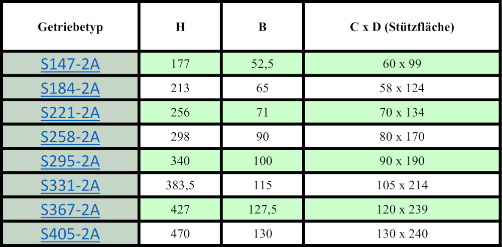
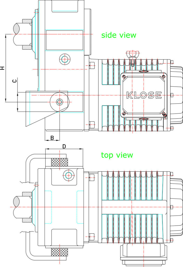
For lateral stops on the housing, a table can be used to specify the distance between the stops and the center of the hollow shaft (advantageous).
Additional design features of a torque arm
The torque arm must be designed in such a way that no additional force is generated in the gearbox (attachment without constraint). It must be taken into account that the neck onto which the gear is pushed may not rotate concentrically. If the gearbox is firmly connected to the support, VERY large forces are created that tear the gearbox bearing apart.
An adjustable clearance must therefore be taken into account between the gearbox and the support arms. Rubber buffers are also installed between the supports and the gearbox to keep the flexibility high and to cushion shocks and vibrations from the gearbox. For particularly heavy applications (heat), the rubber buffers are also replaced by disk springs.
The following illustration is intended to show some of the torque supports that have been implemented. The possibility of screwing the support (comparable to a base plate) under the gear opens up a great deal of scope.
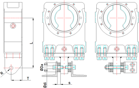
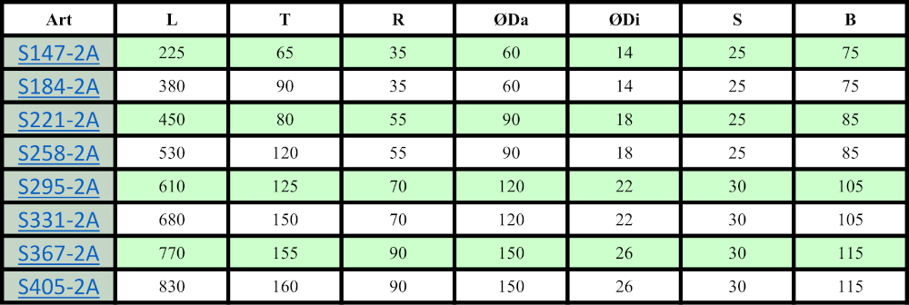
Rubber Buffer Examples of Dimensions
The dimensions of this type and the corresponding buffer size can be found in the table below. Make sure that the ambient temperature for rubber buffers does not exceed 60°C. When using synthetic plastics, an ambient temperature of 80°C can also be reached. The buffers should be oil resistant and should be protected from excessive heat, strong light, oxygen and ozone. With regular heavy loads, they rub themselves down mechanically. This leads to increased play and no longer protects against impacts. Buffers must be monitored and, if necessary, changed regularly.